
Part 9
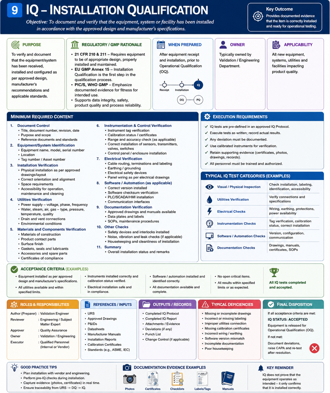
The required lifecycle sequence is:
URS → Risk Assessment → DQ → FAT → SAT → IQ → OQ → PQ → Qualification Summary → GMP Release
The fundamental IQ question is:
Has the equipment/system been installed correctly at its intended location in accordance with the approved design, manufacturer’s recommendations, applicable GMP requirements, and controlled engineering documentation?
9.1 What Is Installation Qualification?
Installation Qualification (IQ) is documented verification that the installed facilities, systems, utilities, equipment, instrumentation, computerized components, and associated supporting elements conform to approved specifications and installation requirements.
IQ establishes the documented installed baseline.
It confirms, as applicable:
- the correct equipment was installed;
- it is installed at the correct location;
- major components are correct;
- product-contact components are appropriate;
- materials of construction are documented;
- utilities are correctly connected;
- instruments are installed and calibrated;
- electrical installation is correct;
- software/firmware versions are identified;
- PLC/HMI/SCADA components are documented;
- safety devices are installed;
- required documentation exists;
- maintenance/calibration requirements are established.
9.2 Purpose of IQ
The purpose of IQ is not merely to prove that equipment is physically present.
IQ should establish:
The final installed configuration is known, documented, traceable, and suitable to proceed to operational testing.
A robust IQ creates a controlled baseline for:
OQ → PQ → Routine Operation → Maintenance → Calibration → Change Control → Periodic Review
9.3 IQ Position in the Lifecycle
User Requirement Specification
             ↓
      Risk Assessment
             ↓
    Design Qualification
             ↓
            FAT
             ↓
          Shipment
             ↓
     Site Installation
             ↓
            SAT
             ↓
     ┌────────────────┐
     │       IQ       │
     └────────────────┘
             ↓
            OQ
             ↓
            PQ
             ↓
 Qualification Summary
             ↓
       GMP Release
IQ therefore converts:
Approved Design
into
Verified Installed Configuration
9.4 IQ vs SAT
SAT and IQ may contain similar activities, but their purposes differ.
| SAT | IQ |
|---|---|
| Site acceptance activity | Formal qualification activity |
| Confirms delivery/site functionality | Establishes qualified installed baseline |
| Focuses on transport/site changes | Focuses on approved installation requirements |
| Often vendor/project driven | Usually qualification/PQS driven |
| Supports readiness for IQ/OQ | Supports progression to OQ |
Where suitable SAT evidence is leveraged into IQ, the rationale should be documented.
9.5 IQ vs OQ
IQ asks:
What has been installed?
OQ asks:
Does the installed system operate correctly?
Example:
IQ
Verify pressure transmitter:
- tag;
- manufacturer;
- model;
- range;
- installation;
- calibration status.
OQ
Challenge the associated:
- measurement;
- alarm;
- control;
- interlock;
- operating range.
9.6 Risk-Based IQ
Not every component requires the same qualification depth.
IQ scope should consider:
- GMP impact;
- product impact;
- criticality;
- quality risk;
- process function;
- data-integrity impact;
- safety impact;
- maintenance/calibration requirements.
High-risk components generally require stronger objective evidence.
9.7 IQ Inputs
Typical IQ inputs include:
- approved URS;
- qualification plan/VMP;
- system-impact assessment;
- quality risk assessment;
- DQ;
- FAT report;
- SAT report;
- approved drawings;
- as-built drawings;
- P&IDs;
- equipment specifications;
- vendor manuals;
- component lists;
- instrument lists;
- calibration certificates;
- material certificates;
- electrical drawings;
- software documentation;
- network architecture;
- spare-parts list;
- maintenance requirements.
9.8 IQ Prerequisites
Before IQ execution, confirm as applicable:
- □ IQ protocol approved
- □ Equipment installed
- □ SAT status acceptable
- □ Critical SAT items closed
- □ Utilities connected
- □ Equipment identification assigned
- □ Drawings available
- □ Instrument list available
- □ Calibration records available
- □ Material certificates available
- □ Electrical installation substantially complete
- □ Software/configuration baseline identified
- □ Safety systems installed
- □ Required test instruments available
- □ Test instruments calibrated
- □ Open project items reviewed
- □ Relevant personnel trained for protocol execution
9.9 Recommended IQ Protocol Structure
A comprehensive IQ protocol may contain:
1. Document Control
- document title;
- IQ number;
- revision;
- project number;
- equipment/system ID;
- location.
2. Approval
- prepared by;
- reviewed by;
- approved by.
3. Objective
4. Scope
5. System Description
6. Responsibilities
7. References
8. Definitions and Abbreviations
9. Prerequisites
10. Test Equipment
11. Equipment Identification
12. Installation Verification
13. Major Component Verification
14. Product-Contact Component Verification
15. Material-of-Construction Verification
16. Surface-Finish Verification
17. Utility Verification
18. Piping/P&ID Verification
19. Electrical Verification
20. Instrumentation Verification
21. Calibration Verification
22. PLC/HMI/SCADA Hardware Verification
23. Software/Firmware Verification
24. Network/Interface Verification
25. Safety-System Verification
26. Documentation Verification
27. Spare-Parts Verification
28. Lubricant Verification
29. Preventive-Maintenance Requirements
30. Calibration Requirements
31. SOP Requirements
32. Training Requirements
33. As-Built Documentation
34. Deviations
35. Open Items
36. Traceability
37. IQ Summary
38. OQ Readiness
39. Approval
9.10 Standard IQ Test Format
Every significant IQ test should follow a consistent structure.
Test ID
Unique test number.
Test Title
Clear description.
Objective
What is being verified?
Prerequisites
What must exist before execution?
Test Method
How will verification be performed?
Expected Result
What result is expected?
Actual Result
What was actually observed?
Acceptance Criteria
What determines Pass/Fail?
Evidence
What objective documentation supports the result?
Status
PASS / FAIL / NOT APPLICABLE
Executed By
Name/signature/date.
Reviewed By
Name/signature/date.
9.11 Equipment Identification
The first IQ activity should establish equipment identity.
Verify:
- equipment name;
- equipment ID/tag;
- manufacturer;
- model;
- serial number;
- location;
- project number where applicable.
Example:
| Attribute | Requirement | Actual | Status |
|---|---|---|---|
| Equipment | Tablet Compression Machine | _____ | |
| Tag | Approved ID | _____ | |
| Manufacturer | Approved Vendor | _____ | |
| Model | Approved Model | _____ | |
| Serial Number | Vendor Record | _____ | |
| Location | Approved Room | _____ |
9.12 Equipment Installation
Verify installation against approved:
- GA drawing;
- layout;
- manufacturer’s instructions;
- design specifications.
Consider:
- location;
- orientation;
- anchoring;
- leveling;
- clearance;
- operator access;
- maintenance access;
- cleaning access.
9.13 Example IQ Test — Installation
Test ID
IQ-INS-001
Objective
Verify that the equipment is installed at the approved location and orientation.
Prerequisites
Approved equipment layout available.
Test Method
Compare installed equipment position and orientation with the approved/as-built layout.
Expected Result
Equipment corresponds to the approved installation arrangement.
Actual Result
Acceptance Criteria
No unexplained discrepancy exists between installed configuration and approved/as-built documentation.
Evidence
Layout drawing number/revision and field inspection record.
Status
PASS / FAIL
9.14 Major Component Verification
Identify significant equipment components.
For a tablet compression machine:
- main frame;
- turret;
- compression rollers;
- feeder;
- hopper;
- lubrication system;
- motor;
- drive;
- reject mechanism;
- control panel;
- PLC;
- HMI.
9.15 Component Verification Table
| Component | Manufacturer | Model | Serial No. | Design Reference | Actual | Status |
|---|---|---|---|---|---|---|
| Main Motor | ||||||
| Drive | ||||||
| PLC | ||||||
| HMI | ||||||
| Lubrication Pump |
The required detail should reflect component criticality.
9.16 Product-Contact Components
Product-contact components require particular attention because they can directly influence product quality.
Verify as applicable:
- identification;
- material;
- surface condition;
- installation;
- certification;
- cleanability.
Examples:
- hopper;
- feeder;
- product chute;
- transfer pipe;
- mixing vessel;
- spray nozzle;
- discharge assembly.
9.17 Material of Construction
IQ should verify specified material-of-construction requirements using appropriate evidence.
Potential evidence:
- material certificates;
- certificates of conformity;
- vendor material list;
- fabrication records;
- approved drawings;
- component identification.
Do not automatically assume that visual appearance proves stainless-steel grade.
9.18 Example Material Verification
| Component | Requirement | Certificate | Actual Material | Status |
|---|---|---|---|---|
| Hopper | Approved MOC | MTC-001 | _____ | |
| Feeder | Approved MOC | MTC-002 | _____ | |
| Product Chute | Approved MOC | MTC-003 | _____ |
The acceptance criterion should correspond to the approved design requirement.
9.19 Surface Finish
Where surface finish is a specified GMP requirement, IQ should verify appropriate evidence.
Potential methods include:
- supplier certificate;
- fabrication record;
- approved surface-finish documentation;
- direct measurement where justified.
Do not introduce an arbitrary universal roughness value if the URS/design does not establish one.
9.20 Gaskets and Seals
Where GMP significant, verify:
- material;
- identification;
- compatibility;
- installation;
- certificates where required.
Typical examples include:
- silicone;
- EPDM;
- PTFE;
- other approved elastomers.
Selection should reflect the approved process and cleaning requirements.
9.21 Utility Verification
Verify all required utilities.
Potential utilities include:
- electricity;
- compressed air;
- vacuum;
- dust extraction;
- nitrogen;
- Purified Water;
- WFI;
- clean steam;
- chilled water;
- process gases.
9.22 Utility IQ Table
| Utility | Requirement | Connection | Actual | Status |
|---|---|---|---|---|
| Electrical | Approved specification | Verified | _____ | |
| Compressed Air | Approved pressure/quality | Verified | _____ | |
| Vacuum | Approved requirement | Verified | _____ | |
| Dust Extraction | Approved requirement | Verified | _____ |
IQ should distinguish between:
Utility connection verification
and
Utility system qualification/performance
when the utility itself is separately qualified.
9.23 Piping Verification
Where piping exists, verify:
- line identification;
- material;
- size;
- routing;
- flow direction;
- valves;
- instruments;
- connection;
- slope where relevant;
- drainability where relevant.
9.24 P&ID Verification
Perform field verification against the approved/as-built P&ID.
A typical method:
- Start from defined system boundary.
- Follow each process/utility line.
- Verify equipment.
- Verify valves.
- Verify instruments.
- Verify flow direction.
- Record discrepancies.
- Update as-built documentation where necessary.
9.25 P&ID Walkdown
A P&ID walkdown should establish:
Drawing = Actual Installed System
Any discrepancy should be:
- documented;
- assessed;
- corrected in field or drawing;
- incorporated into controlled as-built documentation.
9.26 Electrical Verification
Verify applicable:
- power supply;
- voltage;
- phase;
- frequency;
- control panel;
- breakers;
- fuses;
- cables;
- wiring;
- terminal identification;
- motors;
- drives;
- earthing;
- electrical drawings.
9.27 Electrical Panel Verification
Example:
| Component | Design Requirement | Installed | Status |
|---|---|---|---|
| Main Isolator | Specified rating | _____ | |
| PLC Power Supply | Approved model | _____ | |
| Drive | Approved model | _____ | |
| Safety Relay | Approved model | _____ | |
| Circuit Protection | Approved | _____ |
9.28 Earthing
Where applicable, verify:
- protective earthing;
- bonding;
- designated earth points;
- installation condition.
Measurement requirements should follow applicable engineering/site standards and approved specifications.
9.29 Instrumentation Verification
Create or verify the instrument register.
For each critical instrument document as applicable:
- tag;
- description;
- manufacturer;
- model;
- serial number;
- range;
- accuracy;
- location;
- calibration status.
9.30 Instrument Register Example
| Tag | Parameter | Manufacturer | Model | Range | Calibration Due | Status |
|---|---|---|---|---|---|---|
| PT-101 | Pressure | |||||
| TT-101 | Temperature | |||||
| ST-101 | Speed | |||||
| LC-101 | Load/Force |
9.31 Calibration Verification
For GMP-relevant instruments, verify:
- calibration certificate;
- instrument identity;
- calibration range;
- calibration points where relevant;
- result;
- calibration date;
- due date;
- reference standard traceability as applicable.
9.32 Calibration Range vs Operating Range
A critical review is:
Does calibration adequately cover the intended operating/qualification range?
Example:
Process operating range:
10–50 units
Calibration performed:
0–100 units
This may be suitable depending on instrument requirements and calibration methodology.
However, calibration evidence should be evaluated against intended use rather than accepted merely because a certificate exists.
9.33 Calibration Status Labels
Verify that instrument status identification is consistent with site procedures.
Typical information may include:
- instrument ID;
- calibration date;
- due date;
- status.
The controlled calibration system remains the authoritative record according to site procedure.
9.34 Test Instruments Used During IQ
Any measuring instrument used to generate qualification evidence should be appropriately suitable.
Document:
- instrument name;
- ID;
- range;
- calibration status;
- due date.
Example:
| Test Instrument | ID | Range | Calibration Due | Used For |
|---|---|---|---|---|
| Multimeter | Electrical | |||
| Pressure Gauge | Utility | |||
| Tachometer | Speed | |||
| Level | Installation |
9.35 PLC Hardware Verification
For PLC-controlled equipment verify:
- manufacturer;
- PLC model;
- CPU;
- I/O modules;
- communication modules;
- power supply;
- cabinet location.
Compare against:
- approved design;
- FAT baseline;
- final hardware list.
9.36 HMI Hardware Verification
Document:
- manufacturer;
- model;
- serial number;
- screen type;
- location;
- communication interface.
The HMI should be uniquely associated with the qualified system.
9.37 SCADA Hardware
Where applicable, verify:
- workstation;
- server;
- client;
- network hardware;
- interface hardware.
For virtualized environments, physical-server verification may be replaced or supplemented by appropriate infrastructure/configuration evidence according to the validation strategy.
9.38 Software Verification
IQ should identify installed software.
Potential examples:
- PLC program;
- HMI application;
- SCADA application;
- database;
- firmware;
- operating system;
- supporting software.
9.39 Software Version Register
| Software | FAT Version | Approved Version | Installed Version | Status |
|---|---|---|---|---|
| PLC Program | _____ | _____ | _____ | |
| HMI Application | _____ | _____ | _____ | |
| SCADA | _____ | _____ | _____ | |
| Firmware | _____ | _____ | _____ | |
| OS | _____ | _____ | _____ |
Unexplained differences require assessment.
9.40 Software Baseline
IQ should establish the approved software/configuration baseline before OQ.
The baseline may include:
Software Name + Version + Build + Configuration + Backup + Checksum/Hash where used by the site’s control strategy
The exact method depends on the system and approved procedures.
9.41 Firmware
Firmware can affect system functionality and should be documented where relevant.
Examples:
- PLC CPU firmware;
- HMI firmware;
- drive firmware;
- instrument firmware;
- communication-module firmware.
Not every firmware version is necessarily GMP critical, but relevant versions should be identified based on risk.
9.42 Network Verification
For network-connected systems verify as applicable:
- network connection;
- IP address;
- hostname;
- subnet;
- VLAN;
- server;
- communication port;
- time server;
- domain;
- firewall arrangements.
Sensitive cybersecurity details should remain controlled according to site procedures.
9.43 Network Architecture
Example:
Tablet Compression Machine
          │
         PLC
          │
         HMI
          │
   Industrial Network
          │
        SCADA
          │
       Historian
          │
      Site Server
IQ establishes that the required architecture is installed.
OQ/CSV subsequently demonstrates applicable functionality.
9.44 Communication Interfaces
Identify interfaces with:
- MES;
- LIMS;
- SCADA;
- historian;
- ERP;
- BMS;
- EMS;
- printers;
- peripheral machines.
Document interface type and configuration where GMP relevant.
9.45 Safety Device Installation
IQ should verify installation of applicable safety devices.
Examples:
- emergency stops;
- guards;
- guard switches;
- safety relays;
- pressure relief devices;
- overload protection;
- safety sensors.
IQ confirms installation.
OQ challenges functionality.
9.46 Emergency Stops
Verify:
- number;
- location;
- identification;
- physical installation;
- accessibility.
Example:
| E-Stop ID | Location | Required | Installed | Status |
|---|---|---|---|---|
| ES-01 | Operator side | Yes | Yes | Pass |
| ES-02 | Rear side | Yes | Yes | Pass |
9.47 Guards
Verify:
- required guards installed;
- correct location;
- secure mounting;
- safety-switch installation where applicable.
Functional challenge is generally addressed during OQ/SAT as appropriate.
9.48 Pressure-Relief Devices
Where relevant, document:
- device ID;
- location;
- set pressure;
- certification;
- installation orientation;
- discharge arrangement.
This can be particularly important for:
- pressure vessels;
- steam systems;
- compressed-gas systems.
9.49 Lubricants
Lubricants should be reviewed where they can affect equipment reliability or potentially contact product.
Document:
- lubricant name;
- manufacturer;
- grade;
- application point;
- food/pharmaceutical suitability where required;
- vendor recommendation.
9.50 Lubricant Register
| Lubrication Point | Lubricant | Grade | Product Contact Risk | Status |
|---|---|---|---|---|
| Main bearing | _____ | _____ | No | |
| Feeder drive | _____ | _____ | No | |
| Potential incidental-contact point | _____ | _____ | Assess |
Selection should be justified by intended application.
9.51 Spare Parts
IQ should verify availability or identification of critical spare parts as required by the project strategy.
Examples:
- sensors;
- seals;
- PLC modules;
- HMI;
- drives;
- motors;
- filters;
- product-contact parts.
The objective is lifecycle maintainability rather than simply counting every spare delivered.
9.52 Critical Spare-Parts Register
| Spare | Part Number | Criticality | Quantity | Storage Location |
|---|---|---|---|---|
| PLC Module | High | |||
| HMI | High | |||
| Sensor | High | |||
| Seal Kit | Medium |
9.53 Vendor Documentation
Verify availability of required vendor documentation.
Potential documents include:
- operation manual;
- maintenance manual;
- installation manual;
- spare-parts manual;
- troubleshooting guide;
- calibration instructions;
- electrical drawings;
- pneumatic drawings;
- software manuals.
9.54 Engineering Drawings
Typical IQ-controlled drawings may include:
- GA drawing;
- layout;
- P&ID;
- piping drawings;
- electrical drawings;
- pneumatic diagrams;
- control-panel drawings;
- network architecture;
- instrument diagrams.
The applicable drawings should represent the final installed configuration.
9.55 As-Built Documentation
One of the most important IQ concepts is:
Qualification should represent what was actually installed—not merely what was originally designed.
Therefore, relevant documents should reach an appropriate as-built state.
9.56 Design vs As-Built
Example:
Design
Valve V-102 shown upstream of instrument PT-101.
Actual Installation
Valve relocated downstream during installation.
Even if technically acceptable, the drawing is no longer accurate.
Required process:
Identify Difference → Assess → Approve → Update Drawing → Verify As-Built
9.57 Preventive Maintenance
Before qualification completion, the organization should understand the equipment’s preventive-maintenance requirements.
Review:
- vendor recommendations;
- lubrication;
- inspection frequency;
- replacement intervals;
- safety checks;
- filters;
- belts;
- seals;
- critical components.
9.58 PM Assessment
A practical PM table:
| Component | Vendor Recommendation | Site PM Required | Frequency | Procedure/Task |
|---|---|---|---|---|
| Main Drive | Inspect | Yes | TBD/Approved | |
| Lubrication System | Inspect | Yes | ||
| Safety Guards | Inspect | Yes | ||
| Filters | Replace | Yes |
Final frequency should be established through the site’s approved maintenance system.
9.59 Calibration Program
GMP-relevant instruments should be incorporated into the site’s calibration program where required.
Document:
- instrument ID;
- criticality;
- calibration frequency;
- range;
- tolerance;
- responsible department.
The initial calibration evidence should connect to ongoing lifecycle control.
9.60 SOP Requirements
IQ should identify SOPs required before routine operation.
Examples:
- equipment operation;
- cleaning;
- assembly/disassembly;
- changeover;
- calibration;
- maintenance;
- backup/restore;
- user administration;
- alarm handling;
- audit-trail review where applicable.
Not all SOPs necessarily need final approval before IQ execution, but required readiness gates should be defined before GMP release.
9.61 Training Requirements
Identify personnel requiring training.
Potential groups:
- operators;
- supervisors;
- maintenance;
- engineering;
- QA;
- validation;
- automation;
- administrators.
Training should be completed before personnel perform activities for which qualification or GMP procedures require demonstrated readiness.
9.62 Training Matrix
| Role | Operation | Cleaning | Maintenance | System Access | Audit Trail |
|---|---|---|---|---|---|
| Operator | ✓ | ✓ | — | ✓ | As applicable |
| Supervisor | ✓ | ✓ | — | ✓ | ✓ |
| Maintenance | Limited | — | ✓ | Limited | — |
| Administrator | — | — | System | ✓ | As applicable |
Actual requirements depend on system intended use.
9.63 Equipment Cleaning Readiness
IQ may verify installation-related cleaning prerequisites:
- removable components;
- cleaning access;
- cleaning tools;
- drainage;
- cleaning-agent compatibility;
- cleaning instructions.
Cleaning validation itself is a separate lifecycle activity where required.
9.64 Equipment Status Identification
Following installation, equipment should be controlled according to site procedures.
Potential status examples:
- Under Installation;
- Under Qualification;
- Qualified;
- Out of Service.
Status controls help prevent unintended GMP use before qualification completion.
9.65 Equipment Logbook
Where required, establish the equipment logbook or equivalent controlled electronic record.
It may capture:
- operation;
- cleaning;
- maintenance;
- breakdowns;
- calibration;
- qualification;
- significant interventions.
The exact requirements should follow the site’s documentation system.
9.66 IQ Deviations
An IQ deviation may arise when:
- wrong component installed;
- material certificate missing;
- utility does not meet specification;
- instrument range differs;
- calibration expired;
- drawing differs from installation;
- software version differs;
- required safety device is missing.
These discrepancies should not simply be overwritten in the protocol.
9.67 IQ Deviation Lifecycle
Unexpected IQ Result
        ↓
Record Deviation
        ↓
Assess GMP / Quality Impact
        ↓
Investigate Cause
        ↓
Determine Corrective Action
        ↓
Assess Other Tests / Systems
        ↓
Implement Correction
        ↓
Approve Retest
        ↓
Retest
        ↓
Close Deviation
9.68 Example IQ Deviation
Requirement
Pressure transmitter range:
0–6 bar
Installed
0–10 bar
Do not immediately conclude:
“Acceptable because 10 bar includes 6 bar.”
Assess:
- required operating range;
- measurement accuracy;
- resolution;
- calibration;
- alarm/control requirements;
- DQ/design specification;
- process risk.
Possible outcomes:
- accept with technical justification;
- revise design documentation;
- replace instrument.
9.69 Missing Material Certificate
Suppose product-contact component certification is missing.
Possible process:
- Record discrepancy.
- Identify component.
- Contact supplier.
- Obtain certificate or equivalent evidence.
- Verify linkage between certificate and component.
- Assess adequacy.
- Close discrepancy.
Do not create unsupported retrospective certification.
9.70 Drawing Discrepancy
Suppose field installation differs from P&ID.
Do not alter the executed IQ record to make it appear that the drawing was always correct.
Instead:
Record discrepancy → Assess actual installation → Determine correct configuration → Update controlled drawing → Verify revised as-built drawing → Close
This preserves data integrity.
9.71 IQ Open Items
Open items may be classified based on risk.
Critical
Prevents progression to OQ.
Major
May allow limited progression only with approved justification.
Minor
Can potentially be closed before final qualification release.
Example:
| Item | Description | Criticality | Required Before | Owner | Status |
|---|---|---|---|---|---|
| 01 | Critical instrument calibration missing | Critical | OQ | Engineering | Open |
| 02 | Final drawing pending | Major | IQ closure | Vendor | Open |
| 03 | Spare label missing | Minor | Project closure | Vendor | Open |
9.72 IQ Acceptance Criteria
Overall IQ acceptance should establish that:
- required equipment/components are correctly installed;
- critical materials are appropriately documented;
- utilities are correctly connected;
- required instruments are installed and appropriately calibrated;
- electrical installation is acceptable;
- software/hardware baseline is established;
- required safety devices are installed;
- required documentation is available;
- critical discrepancies are resolved;
- outstanding items are appropriately assessed;
- the system is ready for OQ.
9.73 IQ Summary Report
The IQ summary should contain:
- Objective
- Scope
- Protocol executed
- Equipment identification
- Tests performed
- Test results
- Deviations
- Retests
- Open items
- Calibration status
- Documentation status
- Software/configuration baseline
- As-built status
- Maintenance/calibration readiness
- Overall conclusion
- OQ readiness
- Approval
9.74 Example IQ Summary Table
| IQ Section | Status | Comments |
|---|---|---|
| Equipment Identification | Pass | Verified |
| Installation | Pass | As-built configuration confirmed |
| Product-Contact Components | Pass | Documentation available |
| Materials | Pass | Certificates verified |
| Utilities | Pass | Connections verified |
| Electrical | Pass | Installation acceptable |
| Instruments | Pass | Critical instruments identified |
| Calibration | Pass | Current |
| PLC/HMI | Pass | Baseline established |
| Network | Pass | Configuration documented |
| Safety Devices | Pass | Installed |
| Documentation | Conditional | Minor open item |
| PM/Calibration Setup | Pass | Requirements identified |
9.75 IQ to OQ Readiness Gate
Before OQ begins, confirm:
- □ IQ executed
- □ Critical IQ tests passed
- □ Critical deviations closed
- □ Required utilities available
- □ Critical instruments calibrated
- □ Safety systems installed
- □ Software baseline controlled
- □ Required configuration established
- □ Critical drawings available
- □ Test equipment available
- □ OQ protocol approved
- □ Remaining open items assessed for OQ impact
9.76 Worked Example — Tablet Compression Machine IQ
The tablet compression machine provides a useful complete example.
Equipment Identification
Verify:
- manufacturer;
- model;
- serial number;
- equipment tag;
- room/location.
Major Components
Verify:
- hopper;
- feeder;
- turret;
- compression rollers;
- motor;
- drive;
- lubrication system;
- reject mechanism;
- control panel;
- PLC;
- HMI.
Product-Contact Components
Verify:
- hopper;
- feeder;
- turret/product path as applicable;
- discharge chute;
- reject chute.
Utilities
Verify:
- electricity;
- compressed air;
- dust extraction;
- vacuum where applicable.
Instrumentation
Verify:
- compression-force sensors;
- speed measurement;
- pressure instruments;
- proximity sensors;
- reject sensors.
Automation
Verify:
- PLC hardware/version;
- HMI hardware/version;
- software baseline;
- network;
- interfaces.
Safety
Verify installation of:
- guards;
- emergency stops;
- safety switches;
- safety relays.
9.77 Compression Machine IQ Matrix
| Requirement | IQ Verification | Evidence |
|---|---|---|
| Correct machine | Manufacturer/model/serial | Nameplate |
| Approved location | Layout verification | As-built layout |
| Product-contact MOC | Certificate review | MTC/CoC |
| Compression system | Component verification | Vendor documentation |
| Feeder | Identification | Component record |
| Motor | Rating/model | Nameplate |
| Compressed air | Connection verification | Utility record |
| Dust extraction | Connection | P&ID/layout |
| Instruments | Tag/range/calibration | Certificates |
| PLC | Hardware/version | System record |
| HMI | Hardware/version | System record |
| Network | Configuration | Network record |
| Guards | Installation | Inspection |
| E-stops | Installation | Inspection |
| Manuals | Availability | Document register |
| PM | Requirements identified | PM assessment |
9.78 Example Full IQ Test — Compression Force Sensor
Test ID
IQ-INS-014
Title
Compression Force Sensor Installation and Calibration Verification
Objective
Verify that the compression-force measurement system is installed in accordance with approved specifications and has appropriate calibration status.
Prerequisites
- equipment installation complete;
- approved instrument list available;
- calibration certificate available.
Test Method
- Identify compression-force sensor.
- Record manufacturer.
- Record model.
- Record serial number.
- Verify installation location.
- Verify measurement range.
- Review calibration certificate.
- Verify calibration status.
- Compare against approved instrument specification.
Expected Result
Installed sensor corresponds to the approved specification and possesses acceptable calibration status.
Actual Result
Acceptance Criteria
The installed sensor shall be identifiable, appropriately installed, within the approved specification and supported by acceptable calibration evidence.
Evidence
- instrument datasheet;
- calibration certificate;
- instrument register.
Status
PASS / FAIL
Executed By
Reviewed By
9.79 Example Full IQ Test — PLC/HMI
Test ID
IQ-AUT-001
Objective
Verify installed PLC and HMI hardware/software identification against the approved system baseline.
Method
Record:
- PLC manufacturer;
- PLC model;
- CPU;
- firmware;
- PLC application version;
- HMI manufacturer;
- HMI model;
- HMI application version.
Compare with:
- approved design;
- FAT baseline;
- SAT baseline.
Acceptance Criteria
Installed hardware/software shall correspond to the approved configuration or any difference shall have an approved documented disposition.
Evidence
- hardware inspection;
- software/version screen;
- controlled configuration record.
9.80 Example Full IQ Test — Utility Connection
Test ID
IQ-UTL-003
Objective
Verify the compressed-air connection to the equipment.
Method
- Identify compressed-air connection.
- Verify connection point.
- Verify line identification.
- Verify approved connection arrangement.
- Measure supply pressure where required using an appropriate calibrated instrument.
- Record result.
Acceptance Criteria
Compressed-air installation shall conform to approved utility requirements.
Evidence
- P&ID;
- utility drawing;
- measurement record;
- test-instrument calibration record.
9.81 IQ Traceability
IQ should contribute to the overall traceability matrix.
Example:
| URS | Risk | DQ | FAT/SAT | IQ | OQ | PQ |
|---|---|---|---|---|---|---|
| URS-001 | RA-01 | DQ-01 | FAT-01 | IQ-01 | — | — |
| URS-012 | RA-05 | DQ-04 | FAT-05 | IQ-08 | — | — |
| URS-025 | RA-12 | DQ-09 | FAT-18/SAT-08 | IQ-20 | OQ-15 | — |
| URS-041 | RA-21 | DQ-15 | FAT-30 | IQ-25 | OQ-22 | — |
Not every URS needs testing at every lifecycle stage.
The matrix should show where adequate evidence exists.
9.82 Leveraging FAT/SAT Evidence in IQ
Controlled FAT/SAT evidence may potentially support IQ when:
- the requirement was adequately tested;
- objective evidence exists;
- test instruments were appropriate;
- acceptance criteria were predefined;
- configuration is unchanged;
- transportation/installation could not invalidate the evidence;
- change history is controlled.
The IQ should explicitly reference leveraged evidence.
9.83 Example of Appropriate Leverage
FAT Evidence
Material certificate for a permanently identified product-contact component.
SAT
Component identity verified after delivery.
IQ
References:
- FAT certificate;
- SAT identity confirmation.
No scientific value may be gained from requesting another duplicate certificate merely because the lifecycle has reached IQ.
9.84 Example Where FAT Cannot Fully Replace IQ
FAT
PLC hardware verified at vendor.
After FAT
Control panel disconnected, transported, installed and site network connected.
IQ
Still verify:
- installed PLC identity;
- hardware configuration;
- software version;
- site connection.
The final installed state matters.
9.85 Common IQ Deficiencies
| Deficiency | Concern |
|---|---|
| IQ is only a checklist | Insufficient objective evidence |
| No URS/risk traceability | Qualification disconnected from requirements |
| Nameplate data missing | Equipment identity uncertain |
| Materials visually assumed | MOC not objectively established |
| Instrument certificate accepted without ID check | Certificate may not belong to installed instrument |
| Calibration range not reviewed | Instrument may be unsuitable |
| Drawings not field verified | Documentation may not reflect installation |
| Software version omitted | Computerized baseline unknown |
| Network ignored | Site architecture incomplete |
| SAT evidence duplicated without rationale | Inefficient qualification |
| FAT evidence blindly accepted | Installation impact ignored |
| PM/calibration not established | Qualified state difficult to maintain |
| Open items uncontrolled | OQ starts on incomplete system |
| As-built documentation missing | Future maintenance/change control compromised |
9.86 Inspector Perspective
An inspector may ask:
Show me how you verified this was the equipment actually installed and qualified.
The organization should be able to show:
URS → Approved Design → FAT/SAT → Equipment Identification → IQ → OQ/PQ
Another question:
How do you know this instrument was calibrated when OQ was executed?
Expected evidence:
- instrument ID;
- calibration certificate;
- calibration date;
- due date;
- IQ instrument register;
- OQ execution date.
9.87 Inspector Question — Software
An inspector may ask:
Which software version was qualified?
A strong answer should identify:
PLC Version + HMI Version + SCADA Version + Relevant Firmware/Configuration + Controlled Backup
If the organization cannot identify the qualified software baseline, maintaining the qualified state becomes difficult.
9.88 Inspector Question — As-Built Drawing
An inspector may select a P&ID and ask:
Show me this line and these instruments in the field.
If the actual installation materially differs from the controlled drawing, the inspector may question:
- engineering change control;
- qualification accuracy;
- maintenance controls;
- calibration coverage;
- system knowledge.
Therefore:
As-built accuracy is a GMP lifecycle control, not merely an engineering housekeeping exercise.
9.89 Inspector Question — Product-Contact Material
An inspector may ask:
How did you establish that this product-contact component is the specified material?
A robust evidence chain is:
URS/Design Requirement
↓
Approved Material Specification
↓
Vendor Certificate
↓
Component Identification
↓
IQ Verification
↓
Controlled Record
9.90 Maintaining the IQ Baseline
IQ should not be considered a one-time historical document disconnected from future operation.
After qualification, changes to the installed baseline may require assessment.
Examples:
- motor replacement;
- PLC replacement;
- instrument replacement;
- software upgrade;
- network change;
- new product-contact component;
- utility modification.
These should enter:
Change Control → Risk Assessment → Qualification Impact Assessment → Required Verification → Updated Baseline
9.91 Like-for-Like Replacement
Even a claimed “like-for-like” replacement should be evaluated according to the site’s change/maintenance procedure.
Consider:
- manufacturer;
- model;
- material;
- range;
- accuracy;
- firmware;
- configuration;
- function.
A replacement should not be assumed equivalent merely because it physically fits.
9.92 Requalification Trigger
Changes to IQ-established attributes may trigger partial requalification.
Examples:
Instrument Replacement
Potential:
- IQ verification;
- calibration;
- affected OQ function.
PLC Upgrade
Potential:
- software/configuration verification;
- regression testing;
- OQ.
Product-Contact Material Change
Potential:
- IQ;
- cleaning assessment;
- process/quality risk assessment.
The extent should be risk based.
9.93 IQ Documentation Hierarchy
A strong IQ package may contain:
IQ Protocol
   │
   ├── Equipment Identification
   ├── Installation Records
   ├── Component Register
   ├── Material Certificates
   ├── Instrument Register
   ├── Calibration Certificates
   ├── Utility Records
   ├── Electrical Records
   ├── Software Baseline
   ├── Drawings
   ├── As-Built P&IDs
   ├── Vendor Documentation
   ├── Deviations
   ├── Raw Evidence
   └── IQ Summary Report
9.94 Good Documentation Practices During IQ
IQ execution should follow applicable GDP requirements.
Ensure entries are:
- attributable;
- legible;
- contemporaneous;
- original/true copy as applicable;
- accurate;
- complete;
- consistent;
- enduring;
- available.
Avoid:
- blank fields;
- undocumented corrections;
- backdating;
- pencil where prohibited;
- unexplained overwriting;
- copied results;
- untraceable attachments.
9.95 Handling Corrections
If an execution error is made in a paper record, corrections should follow approved GDP procedures.
The original entry should remain readable.
Electronic corrections should similarly maintain appropriate traceability.
Qualification data should never be manipulated to make a failed test appear to have passed initially.
9.96 Photographic Evidence
Photographs can support IQ for:
- equipment nameplates;
- component identification;
- installation;
- utility connections;
- labels;
- safety devices.
However:
A photograph should support controlled verification, not replace the protocol’s documented assessment.
Photos should be identifiable and traceable to the relevant test where used.
9.97 IQ Inspection-Readiness Checklist
Protocol
- □ Approved IQ protocol
- □ Defined objective
- □ Defined scope
- □ Responsibilities assigned
- □ Acceptance criteria established
Equipment
- □ Name
- □ Tag
- □ Manufacturer
- □ Model
- □ Serial number
- □ Location
- □ Orientation
- □ Leveling/anchoring where relevant
Components
- □ Major components
- □ Product-contact parts
- □ Materials
- □ Surface finish where specified
- □ Gaskets/seals where significant
Utilities
- □ Electricity
- □ Compressed air
- □ Vacuum
- □ Dust extraction
- □ Water/steam/process utilities where applicable
- □ Connections
- □ Identification
Piping
- □ P&ID verified
- □ Line identification
- □ Flow direction
- □ Valves
- □ Instruments
- □ As-built status
Electrical
- □ Panel
- □ Supply
- □ Wiring
- □ Protection
- □ Motors
- □ Drives
- □ Earthing
- □ Drawings
Instrumentation
- □ Instrument register
- □ Tags
- □ Manufacturer/model
- □ Range
- □ Accuracy where required
- □ Calibration
- □ Due dates
- □ Calibration range suitability
Automation
- □ PLC hardware
- □ PLC software
- □ HMI
- □ SCADA where applicable
- □ Firmware
- □ Software versions
- □ Configuration baseline
- □ Backup
- □ Network
- □ Interfaces
Safety
- □ Guards
- □ Emergency stops
- □ Safety switches
- □ Safety relays
- □ Pressure-relief devices where applicable
Lifecycle
- □ Manuals
- □ Spare parts
- □ Lubricants
- □ PM requirements
- □ Calibration requirements
- □ SOP requirements
- □ Training requirements
- □ Equipment status controls
Documentation
- □ GA drawing
- □ Layout
- □ P&ID
- □ Electrical drawings
- □ Instrument list
- □ Component list
- □ Material certificates
- □ Calibration certificates
- □ Software records
- □ As-built documents
Closure
- □ All tests executed
- □ Actual results recorded
- □ Evidence traceable
- □ Deviations documented
- □ Failed tests retained
- □ Retests controlled
- □ Open items assessed
- □ Critical issues closed
- □ IQ summary completed
- □ OQ readiness approved
9.98 IQ Readiness Decision Tree
IQ Execution Complete
        ↓
Any Critical Failure?
   ┌────┴────┐
  Yes        No
   │          ↓
Hold OQ   Open Items?
   │       ┌──┴──┐
Correct   Yes    No
   │       │      │
Retest  Assess   ↓
   │     Impact  IQ Approved
   │       │      │
   └───────┴──────┘
           ↓
       OQ Readiness
9.99 Golden Rule of Installation Qualification
The strongest IQ principle is:
Do not qualify what the drawing says should be installed. Qualify what is actually installed—and ensure the controlled documentation accurately represents that final installed state.
IQ should establish an objective, traceable baseline linking:
Design → Equipment → Components → Materials → Utilities → Instruments → Calibration → Automation → Software → Safety → Documentation → As-Built Configuration
9.100 Part 9 — Key Takeaway
Installation Qualification is the formal lifecycle stage that transforms a delivered and site-accepted system into a documented qualified installation baseline.
A robust IQ establishes:
1. Identity
The correct equipment and critical components are installed.
2. Physical Installation
Location, orientation, assembly and connections correspond to approved requirements.
3. GMP Construction
Product-contact materials and other critical construction attributes are documented.
4. Utilities and Electrical Systems
Required services are appropriately installed and connected.
5. Instrumentation
Critical instruments are identified and have appropriate calibration status.
6. Automation Baseline
PLC, HMI, SCADA, firmware, software, network and relevant configuration are documented.
7. Safety
Required safety devices are physically installed.
8. Lifecycle Controls
Maintenance, calibration, SOP, training, spare-parts and documentation requirements are established.
9. As-Built Accuracy
Controlled engineering documentation represents the actual installed system.
10. OQ Readiness
Critical installation deficiencies are resolved before functional qualification begins.
The final evidence chain is therefore:
URS → Risk Assessment → DQ → FAT → SAT → IQ Installed Baseline → OQ Functional Verification → PQ Performance Verification → Qualification Summary → GMP Release
Part 10 — Operational Qualification (OQ) is the next stage. It should move from verifying what is installed to challenging how the installed system actually operates, including operating ranges, upper/lower limits, alarms, interlocks, sequences, controls, failure modes, recovery, recipes, user access, audit trails, electronic records, backup/restore and computerized-system functions, with strong emphasis on worst-case and boundary testing, objective evidence, deviation handling, and risk-based traceability.
About the Author
Ramesh Palav is a pharmaceutical professional with 20+ years of industry experience in manufacturing, GMP, quality systems, validation, compliance, and operational excellence. Through Pharma Manufacturing Hub, he shares practical insights on pharmaceutical careers, manufacturing, quality, validation, Pharma 4.0, AI, and professional development.
His goal is to help students, freshers, experienced professionals, and career-break professionals build the knowledge and skills needed to succeed in the pharmaceutical industry.